Improve HYP Production
High strength steels are offering many advantages to the pipeline industry. These steels allow for the use of thinner pipe at higher operating pressures. These steels can also drive down total construction costs. However, as pipeline owners and designers look to these new steels, they are presenting a challenge for the welding and fabricating industry that must respond with cost-effective ways of joining them. To complicate the matter, these high performance steels have surpassed conventionally fabricated weld metal in terms of hydrogen crack resistance and fracture toughness.

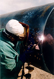
Since SMAW has been adequate to produce safe, economic pipelines, the industry has been slow to adopt the more recent advances in welding process development. SMAW i.e. Cellulosic electrodes has remained the most common process for welding pipelines and has a greater ability than other processes to accommodate non-ideal conditions such as poor fit-up to a change in terrain. However, as the strength of the steel increases there has become a greater risk of failure, either due to hydrogen cracking or reduced toughness. It is this risk of hydrogen cracking that is the main issue with the cellulosic SMAW electrodes in higher strength applications.
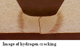
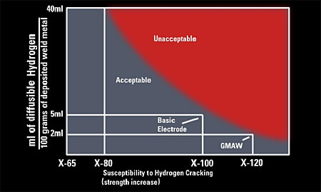
Hydrogen dissolves in the molten puddle during welding. Upon cooling, diffusable, as opposed to chemically bound, hydrogen can cause porosity during solidification and cracking in the finished weldment. This moisture originates primarily from the moisture and organic components. Attempts to adapt welding processes and procedures to X-80 and higher strength steels must be assessed. To take advantage of the pipe strength, the weld metal must either match the strength of the pipe or exceed it. The welding process and consumables must be controlled to minimize the risk of brittle fracture in the weld during pipeline fabrication and the resulting risk of hydrogen cracking. In addition, the demands of higher productivity
Introduction
Low hydrogen manual processes suitable for the pipeline girth welding have been available for some time, but despite their availability and advantages in terms of reduced crack susceptibility, they have rarely been used in production up to the present time.
With the advent of the new high strength steels such as X-80, any large pipeline project will, consider if not use, these grades of pipe steel, and therefore contractors and engineers must accept the advancements in the welding processes.
New, high strength steels are offering many advantages to the pipeline industry. These steels allow for the use of thinner pipe at higher operating pressures. These steels can also drive down total construction costs. However, as pipeline owners and designers look to these new steels, they are presenting a challenge for the welding and fabricating industry that must respond with cost-effective ways of joining them. To complicate the matter, these high performance steels have surpassed conventionally fabricated weld metal in terms of hydrogen crack resistance and fracture toughness.
Manufactured using a combinations of heat treatment and mechanical treatment that produce higher strength without significant higher alloy. Such advancements in thermomechanical processing in steels (TMCP) make it possible to achieve the balance in strength and toughness, but with a greater resistance to heat affected zone cracking.
With all the positive factors regarding the higher yield materials the biggest challenge is how to weld these steels. The pipe steel is no longer the limiting metallurgical factor. For example, steels are no longer as sensitive to hydrogen cracking as are conventional weld materials. This is why it is important to examine hydrogen cracking and potential solutions in relation to the weld metal.
Hydrogen Cracking
It is the main issue with cellulosic SMAW electrodes in higher strength applications. This hydrogen originates primarily from the burning of the electrode coating, which contains moisture and organic components Hydrogen dissolves in the molten puddle during welding. Upon cooling, diffusable, as opposed to chemically bound, hydrogen can cause porosity during solidification and cracking in the finished weldment. That is why it is critical that hydrogen levels be minimized for the weld to be considered sound.
With respect to the hydrogen issue, the challenge is to minimize the risk of weld metal cracking by controlling the factors know to be influential.
1. Minimize the amount of hydrogen that is available through judicious selection of consumable and/or welding process controls.
2. Minimize stresses, both residual and applied.
3. Minimize weld metal strength, thus controlling the susceptibility of the microstructure. Some industries have successfully employed undermatching strength weld metals, contingent upon design requirements.
It should be noted that with respect to hydrogen, the risk of cracking might be minimized, but it is impossible to eliminate. Since all steel microstructures are susceptible somewhat to cracking, it simply becomes a question of controlling hydrogen and stress levels simultaneously.
A report published in 1996 by The Welding Institute titled “ Evaluation of Low Hydrogen Processes For Pipeline Construction in High Strength Steel”, (PR-164-9330) which investigated suitable processes for the welding of X80 grade pipe reported,
"The most successful root welding performance was obtained using the Lincoln Electric STT® power source and the LA90 electrode wire. The STT power source provided very precise control of short circuiting metal transfer, which resulted in good handling characteristics, well-fused beads, minimal spatter and lower fume emissions. The TWI welder involved in the trials was depositing satisfactory root beads within two hours of being introduced to the welding machine. The root welding speeds were comparable with cellulosic."
What is the Proper Way of Joining Pipe?
It depends on many variables, including fit-up, accessibility, terrain, if it’s a tie-in or crossing, whether it is a repair weld, the welder skill and a number of other factors.
Each possible welding process has its own merits, and there is no single clear-cut answer for every application. Attempts to adapt welding processes for higher strength steels must be considered. In addition, the demands of higher productivity and quality are always present.
Root Pass Welding
Traditionally the welding of the root and hot pass have been completed using a high hydrogen cellulosic electrode.
However on X-80 type material, restrictions do apply. Deposition of small weld passes at high travel speeds are possible with sufficient preheat temperature control.
Preheat is required to slow the rate at which the weld cools, thus allowing hydrogen to diffuse, in addition, the use of preheat can also help control residual stresses in the weld zone.
While this approach sacrifices nothing in terms of deposition rate compared with current practices on lower yield pipe, the need for potentially high levels of preheat can limit overall productivity.
It is currently not advisable to weld with cellulosic electrodes on X-80 that is more than 10mm in thickness.
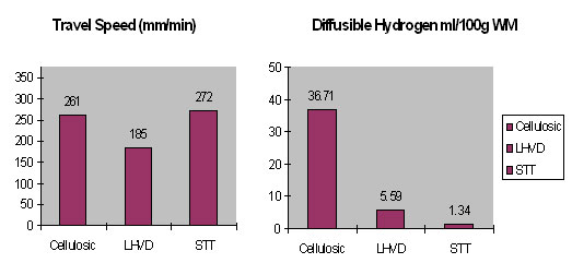
The use of basic coated “low hydrogen” electrodes for the root pass weld as productivity issues. Albeit they can produce one-tenth the level of hydrogen compared to a cellulosic electrode, the major disadvantage is that the process is slow compared to any other process, apart from Gas Tungsten Arc Welding (GTAW).
Whilst SMAW as been used, and can be used to create acceptable quality welded joints in the high yield steels, productivity issues make SMAW less attractive than welding with a continuous wire process. Since there is a strength ceiling for the cellulosic electrodes because of the high hydrogen levels, and the poor productivity levels with the basic low hydrogen electrodes, alternatives are required.
Welding Productivity
For field welding of pipelines, it is the elapsed time to remove the pipe clamp, which is the critical indicator of welding productivity. The elapsed time will depend on a number of factors including the strength of the weld deposit, the dimension of the welded ligament and the level of hydrogen present.
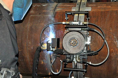
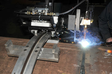
The root pass welding speed determines the advancement of the construction, and therefore it is the focal point that lends itself best to technological advances. Mechanized systems can weld faster than manual or semi-automatic, provided the requisite care is taken in joint preparation and fit-up to ensure proper process control.
Preparation and Presentation
In Manual and Semi – Automatic welding, the journeymen or pipe fitter has a tolerance in which the welder can compensate for variation in the joint fit – up. In automatic welding that tolerance is more critical, therefore the bevel geometry, and the line – up and spacing needs to be addressed mechanically.
Preparation – Pipe Facing Machines (PFM’s). The roundness and consistency of the joint are more important when making welds using an automated system. Therefore, the use of a PFM in the field is critical to the success and quality of weld, regardless of whether an internal or external root pass machine is used.
Presentation – After preparation two approaches maybe adopted. One approach is to have the root pass welded in the short arc mode on the inside of the pipe with multiple torches. Production rates can be high, but the process requires great care in joint preparation and fit-up. If this is not perfect, then there is a greater chance that many poor quality welds will be made in a very short period of time.
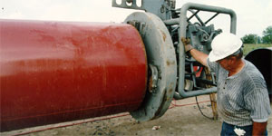
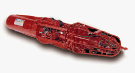
A second option is to weld the root pass from the outside utilizing an internal line-up spacer clamp, shown above. The sequence of operation is somewhat different to conventional internal clamps were as the Internal line – up / Spacer clamp, is first located into the pipe, and the first set of internal chucks are expanded into a hard chuck. This aligns the clamp with the ID of the pipe, and takes out any ovality.
The second step is to bring into close proximity the next section of pipe. The second set of chucks are then engaged, which grabs the piece of pipe in a soft chuck. Once in a soft chuck, the clamp is spaced in, which forces the two pipes together.
With one set of the chucks been in a soft state, they allow the pipe to move, so that the two faces of the pipe are butted up tight together. The second set of chucks are then actuated into a hard chuck, which again takes out any ovality. The final stage is to space the clamp out, giving the journeymen/fitter a predetermined uniform gap around the pipe.
Gas Metal Arc Semi-Automatic / Automatic welding processes provide an opportunity for increased productivity and deposition rates by virtue of fewer stop/starts. However, traditionally the short-circuit mode as been identified as having a risk of lack of fusion.
Normal short arc welding is considered to be low heat input. However, the current, which is proportional to wire feed speed, can be increased to give higher input and increased penetration. This can result in a fine balance between too little and too much, and requires considerable operator skill so to avoid defects like internal “whiskers”. There needs to be enough heat to fuse the inside edges but not so much as to “blow through”. The operator has to ride the puddle with the arc to achieve the correct penetration and does not have much room for deviation.
These defects can easily be detected by industry standard non-destructive evaluation, such as radiography and ultrasonic inspection. On the other hand, GMAW does have its advantages. Since hydrogen levels with GMAW are typically low, pre-heat requirements are minimal and cracking is rarely an issue.
Controlled Short Circuit Transfer (STT)
One area of recent innovation that as provided operational advantage on high strength pipe, is on external open gap root pass utilizing the controlled short circuit transfer mode
The controlled short circuit transfer mode is different in several ways from the conventional CV process. The STT power source operates neither in constant current (CC) nor constant voltage (CV), rather it is a wide – band width, current – controlled machine wherein the power to the arc is based on the instantaneous arc requirements.
In principle, it is a power source, which has the capability of delivering and changing electrode current in the order of microseconds.
How Does It Work?
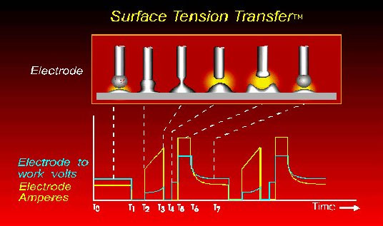
The electrode current supplied by the SurfaceTension Transfer power source is guided by the state of the arc voltage.
Background current (T0 – T1). This is the current level of the arc prior to shorting to the weld pool. It is a steady current level between 50 and 100A
Ball time (T1 – T2). When the electrodes initially shorts, the “arc voltage” detector provides a signal that the “arc” is shorted. The background is further reduced to 10A for approximately 0.75 m/s
Pinch mode (T2 - T3). Following the ball time, a high current is applied to the shorted electrode in the form of an increasing, dual – slope ramp. This accelerates the transfer of the molten metal from the electrode to the weld pool by applying electric pinch forces
dv/dt calculation (T2- T3). This calculation is included within the pinch mode. It is the calculation of the rate of change of the shorted electrode vs. time, when this calculation indicates that a specific dv/dt value has been attained, indicating that fuse separation is about to occur, the current is then reduced to 50 A in microseconds. (Note this event occurs before the shorted electrode separates. T4 indicates the separation has occurred, but at a low current)
Plasma boost (T5 – T6). This mode follows immediately the separation of the electrode form the weld pool. It is a period of high arc current where the electrode is quickly "melted back"
Plasma (T6 – T7). This is the period of the cycle where the arc current is reduced from plasma boost to the background current level
The process can be applied to either semi-automatic or automatic applications. It operates in the short circuiting region with various shielding gas blends including 100% carbon dioxide for mild steel, as well as various blends of argon/oxygen, argon/carbon dioxide and argon/helium for stainless steel.
Fill and Cap Pass Welding
Cellulosic covered electrodes may still be used if care is taken in controlling preheat and interpass temperatures, with pipe wall thickness up to and including 10mm on X-80. It is not currently advisable to attempt to weld on thickness greater than 10mm because increased restraint and cooling rates are expected to increase the risk of weld metal hydrogen cracking.
Low hydrogen vertical-up electrodes are not normally used for transmission pipeline production welds, due to the low productivity.

It is now become more common, especially in Europe, to use the basic Low Hydrogen vertical Down electrodes for the weld of high yield pipe. LH-D electrodes are designed for any vertical down welding application where low-hydrogen weld metal is demanded, such as high strength pipe welding. Although these are designed specifically for vertical down welding of pipe joints, the LH-D are useful in any vertical down application where a low-hydrogen deposit is required.
The low-temperature impact properties are superior to cellulosic electrodes that possess the same level of strength. As downhill electrodes, they have significantly greater deposition rates than both vertical - up electrodes and downhill cellulosic electrodes of equal diameter; this increases the potential for greater productivity, while meeting high strength requirements.
Semi-Automatic
Processes can be categorized into, gas shielded and shelf shield.
Gas shield GMAW would typically be fully mechanized, because the welding area needs to be protected from the elements. If the contractor is prepared to protect the welding area, it is more feasible to use a fully automatic set-up.
This leaves FCAW-S (self-shielded) as the only serious semi – automatic welding for consideration, the obvious advantage is that you gain from the reduction in stop starts, without the need for ancillary shielding.
Mechanized Processes
GMAW and FCAW-G are the most common means of mechanized welding for fill and cap passes on pipe. The current techniques are based on either short arc or pulsed spray transfer with high wire feed speeds.
The advancement and development of welding power source technology could conceivably yield significant productivity improvement
Along with the improvements and welding characteristics of solid or cored electrodes, it will be possible to improve the welding performance and deposition.
Mechanized GMAW holds tremendous potential for the future, because it requires less training, and results in lower hydrogen levels, higher productivity and better quality.
Conclusions
The direction of the welding community must follow two clearly define channels:
1. Enhancement of current welding processes: by advancing the designs of current basic low hydrogen manual and semi-automatic consumables, to better control hydrogen, strength and toughness. Although this methodology may prove successful for the X-80 applications, the increasing demand for greater hydrogen control and higher toughness, will likely drive the industry to new technological advances in consumables and processes.
2. Innovation in welding consumables and welding power source design. Pipe contractors and fabricators have much to benefit by adopting these new technologies:
The development of the Controlled Short Circuit Transfer utilizes the latest technology to enable previously unattainable control over several arc variables
Advances in pipe spacing, clamping, Bug and Band systems and multiple arc equipment can save time, increase quality and reduce costs for pipeline projects
Advancements in solid and cored electrodes will limit hydrogen and will enable manufacturing flexibility
With quality and productivity in mind, Lincoln Electric is in the forefront of pipe welding processes and is constantly seeking solutions for these high strength steel challenges.
References
TWI: Evaluation of Low Hydrogen Processes for pipeline Construction in High Strength Steel – PR-164-9330
Elliot K. Stava: 1993 The Surface Tension Transfer® power source, A New, Low –Spatter Arc Welding Machine. Welding Journal 72(1): 25-29

