How to Read the LASER Screen
Overview: The VRTEX® has the ability to give a user instant feedback which is one of the many attributes to this machine. Instant feedback can help the user learn faster than a traditional welder training program. The instant feedback allows the user to perform a weld, look at the feedback, make corrections and move on to the next weld in seconds. Correcting and repeating areas such as body position or movement over and over allows the user to gain muscle memory while not wasting weld materials.
Understanding the LASER:
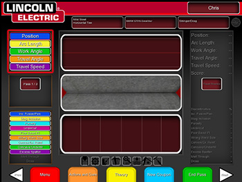
The Live Action Student Evaluation Report (LASER) screen is a valuable tool for the instructor. This graphical representation of the weld gives the user and the instructor immediate, in-weld data based on the techniques of the welder. The report can be used for real-time feedback as well as a report card that can be saved for the weld performed.
Tips on how to read and understand the screen:
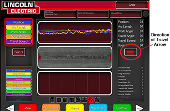
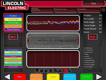
In the flat positions (Flat Plate and 1G), the horizontal positions (2F and 2G) and overhead positions (4F and 4G) the LASER screen appears in the horizontal position. The graph can be read in the direction of travel. This is located to the immediate right of the weld image in the center of the screen.
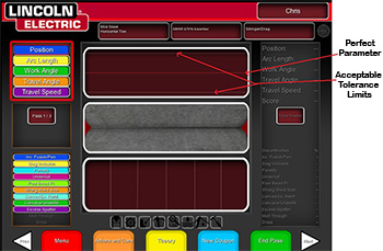
The red line in the middle of the graph represents the “perfect” parameter. For example; if the work angle is set at 45 degrees, the red line represents exactly 45 degrees. The white lines located at the top and bottom of the same graph represent the acceptable tolerances/parameters, which can be adjusted in the tolerance settings. (See the operator’s manual for instructions on how to change tolerances.) The white lines represent the plus and minus tolerance set by the instructor that represents the acceptable movements allowed for a “passable” weld. Since most people cannot hold a perfect 45 degrees, the tolerances can be adjusted to make acceptable welds within a range. For example; if the work angle is 45 degrees, the acceptable tolerances can be set at plus or minus 5 degrees. That allows the user to move between 40 and 50 degrees and still receive a passing score.
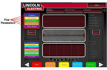
Five parameters that assist the user in understanding the weld requirements:
- Position on the joint – Blue line
- Contact Tip to Work Distance (CTWD) or Arc length – Yellow Line
- Work Angle – Green Line
- Travel Angle – Orange Line
- Travel Speed – Purple Line
Keeping the proper angles, distances and speeds will result in each colored line or tracking to appear on the graph close to the red center line. The further away or more inconsistent the performance from the expected tolerance (red line) the lower the score the user will receive.
If any of the lines fall outside (above or below) the white acceptable lines the user will receive discontinuities in the weld. For example; if the user is welding a 7018 weld and they extend the Arc Length outside the acceptable tolerances, they will most likely receive porosity in the weld. When the user brings the Arc Length closer or in-range, the porosity will stop.
Understanding the Graph:
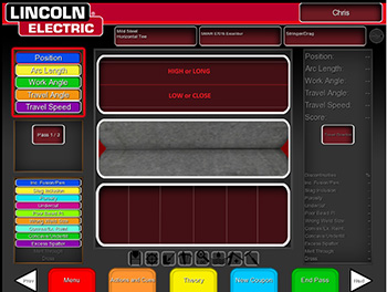
Reading the graph is simple. When the graph is in the horizontal position, any line above the red center line is high or long. For example; if the yellow CTWD line is above the red center line the user has a long CTWD or Arc Length indicating the user needs to push the electrode closer to the work piece. If the lines are below the red center line the user is low or close. Another example; if the users work angle is too low, the green line will appear below the red center line indicating the user needs to lift their work angle to receive a better score.
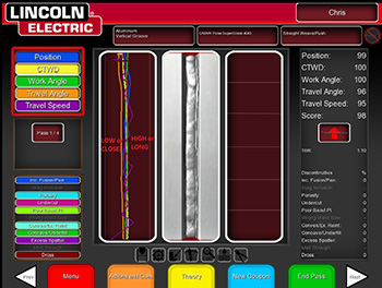
For the vertical welds the graph will also show in the vertical position. The red center line represents the same exact number. Reading the vertical graph is just as easy as the horizontal graph. The right side of the red center line represents high work/travel angle, high travel speeds or out of position to the right side of the center of the joint. Lines to the left of the red center line represent close CTWD or Arc Length, low work/ travel angles and position to the left of center of the joint.
Helpful Tips:
When reviewing the graph, you can highlight specific areas or lines, by removing the other areas or lines from the screen. This is done by using the joystick on the VRTEX® to move to the upper left portion of the screen with the parameters colors and names. You can select, add or remove the parameters you want visible with the red button next to the joystick. This allows the instructor to focus in on one specific learning area with the student. Once that training discussion is completed, you may want to enable a visual cue to assist the student correct or refine the area of interest.
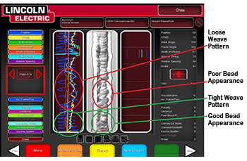
During a weave weld, watch the position (blue line) to see how tight the weave pattern is being performed. A wide pattern represents a ropey bead appearance and a tight pattern represents a smooth bead appearance. The position line can also tell the user if the weld is centered on the joint. If the line is split equally by the red expected tolerance line then the weld is centered on the joint. If it favors one side or another the weld is off center.

