Are Tactile Seam Tracking Systems Right for You?
Brian Butler, Automation Manager, Arc Products, Inc.
In the last few years, many manufacturers once again have become aware of the advantages of using seam tracking systems. For companies to stay competitive in today’s market, production facilities must become lean and efficient. Tactile seam tracking systems help manufacturers achieve this goal with a relatively small capital investment. Companies in countries that have historically added more labor to a particular welding project, in hopes of meeting required production rates, also have realized the benefits tactile seam tracking systems offer.
First developed in the 1960s, seam tracking systems have undergone constant changes to keep up with technology and to add features required by modern welding applications.Tactile systems track the seam using a sensor with a tip that rides in the seam, much like a needle follows the groove of a phonograph. When small changes in the location or alignment of the seam move the sensor’s tip, the system responds by moving the cross slides and torch to maintain the correct position over the seam. Seam tracking systems are used in all welding processes, but the primary applications include GMAW, FCAW and SAW. Seam tracking systems also are quite versatile; at times they can be used beyond welding applications for other manufacturing needs, such as applying adhesives.
Seam tracking systems are ideal for applications that are repetitive in nature. In such applications as beam fabrication or tank and pressure vessel manufacturing, these systems provide a significant increase in quality and productivity, while reducing scrap / rework and freeing the operator to do other tasks in preparation for the next part to be welded. With advances in welding power sources and arc technology, weld travel speed is increasing beyond the operator’s ability to manually position the torch accurately over the seam. This makes a seam tracking system nearly a necessity.
Tactile seam tracking systems offer a good balance between cost and flexibility and are offered in two models: standard and advanced. When choosing the appropriate seam tracking system for your application, follow this simple, four-step process:
- Determine the payload and stroke length requirements
- Select the desired level of automation
- Select the sensor tip to match your seam configuration
Step 1 –Payload Requirement: Determine the weight the system will carry and select the appropriate cross slide. Cross slides are offered in weight capacities of 40 (18), 250 (113) and 450 (204) pound (kg) models. Be sure to select a model with a rating higher than your requirement. Pricing differences between models is usually not significant, so if your requirements are near the rating of one of the cross slides, upgrade to the next model to provide much longer service life and less maintenance.
Step 2 –Stroke Length Requirement: Determine the stroke length of the cross slide you will need. The 40-pound (18 kg) model is typically offered in 3” x 3” (8 cm x 8 cm) and 6” x 6” (15 cm x 15 cm) stroke lengths, whereas the larger models are offered in standard 5” x 5” (13 cm x 13 cm) or 10” x 10” (25 cm x 25 cm) stroke lengths. The first number represents the horizontal stroke length and the second is the vertical stroke length (use “H” before “V”, just as in the alphabet, to be sure your order is built correctly).
Custom stroke lengths are available in 5” (13 cm) increments up to 60” for the 250 (113) and 450 (204) models. The cross slides can be configured with each axis having a different stroke length to accommodate specific applications, where, most commonly, more horizontal stroke length is needed—a 20” x 10” (51 cm x 25 cm) or 30” x 5” (76 cm x 13 cm), for example.
Step 3 –Level of Automation: Select the level of automation—fully automatic or semi-automatic. Selecting fully automatic will require use of an advanced model, which can take full advantage of the remote inputs and outputs. The standard model would fit the semi-automatic selection, providing basic seam tracking but requiring the operator to manually start and stop the welding process.
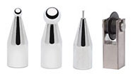
Step 4 –Sensor Tip Selection: Selecting the appropriate tip is simple, primarily involving matching a tip size to the seam type and the material thickness.
Each system is provided as a kit consisting of several components; see Table 1 for a list of components and typical price ranges for pre-configured systems. As you will notice in this table, the standard seam tracking systems are the most affordable. The return on investment can be as short as 5 to 6 months, depending upon current production rates and rework at your facility.
Table 2 lists the features and capabilities of each model of seam tracking systems. As mentioned earlier, the standard systems offer basic seam tracking features. This standard model will search for the seam by driving straight down until the sensor contacts the work piece. In fillet welds or lap joints the Sidetrack function is enabled to provide a left or right bias to keep the sensor’s tip against the seam’s edge. In this case, the system will drive downward at a 45-degree angle until the sensor contacts the work piece and is stopped horizontally by the seam’s edge.
In either case, once this basic system finds the seam, the operator must start the welding process, i.e., start the welding power source, wire feeder, carriage / welding lathe, etc. The standard seam tracking system is ideal for simple applications to gain quality, reliability and productivity without the added expense of fully automating the welding station.
Advanced systems offer the same features as the standard system, but add features and flexibility by providing sequence timers and inputs and outputs to control other components. For a complete list of inputs and outputs with descriptions (see Table 3). Sequence timers and other features minimize the need for additional controllers, such as programmable logic controllers (PLC), allowing an advanced model to be the principle sequence controller. If a PLC is needed in complex applications, an advanced model communicates with them, allowing easy integration and providing the PLC with process awareness.
Lap joints, “V” grooves, and fillet welds are all ideal joint types for the tactile seam tracking systems, but there are some configurations that are not ideal, such as butt joints without a bevel. In this configuration, the seam does not have a wide enough opening to hold the sensor’s tip captive and, therefore, will not be able to reliably track the seam horizontally. Advanced systems offer the solution to automatically track vertically, maintaining a consistent torch height, while the operator manually controls horizontal placement of the torch via the joystick control.
Advanced systems have a feature called tack cut-off, which enables the system to weld in applications where tacks are used to hold the parts in place. The tack cut-off feature senses the tack in the weld by the rapid movement of the sensor’s tip as it rides over it. While riding over the tack, the system locks movement of the torch to maintain the desired position. As the sensor passes over the tack and falls back into the seam, the tack cut-off feature unlocks movement of the torch and begins tracking again.
Another application that may create an obstacle is multi-pass welding. Multi-pass welding has been an issue for seam tracking systems because the seam is not well defined after the first pass. However, by using a “Y”-type sensor tip, the system will track the seam very well. In fillet welds for beam fabrication, for example, a “Y”-type sensor tip could be employed to sense the seam at two different points. One tracking point of the “Y” tip would sense horizontal movement from the flange, while the other would sense vertical movement from the webbing. In tracking the seam in this manner (out of the seam), the multi-pass weld beads will not affect the system’s ability to track the seam. A larger diameter ball tip can be used instead of a “Y” tip with similar results.
Multi-pass welds on “V” grooves, or deep grooves, offer a greater challenge, but these also can be overcome with great results. With advanced systems, the sensor can track the first pass, usually the most critical, without issue. Subsequent hot and fill passes can be tracked using a left or right bias (sidetrack) to stagger the beads as the passes are run. But on cap passes, the system must be locked out horizontally, to prevent automatic torch movement from the sensor, because there is no longer a well-defined seam to hold the sensor’s tip captive. An input called horizontal auto-disable is used and, when enabled, locks the sensor’s ability to move the torch left or right while still tracking vertically and maintaining a consistent torch height. Enabling this feature allows the operator to manually position the torch left or right for cap passes using the joystick. By using this method, the critical passes are tracked reliably and quality is improved significantly over positioning each weld pass manually.
Seam tracking systems are relatively easy to set up, usually taking only one or two days until completion. Upgrading an existing system, where the fixture and part presentation to the torch is already established, could take as little as a half day to install and configure.
The standard model configuration is easy. Requiring no interface between the system and other components of the station, the installation consists of mounting the cross slides and control unit and configuring the torch and sensor for optimum welding and tracking. This process also is used to setup the advanced model, but because advanced systems can be interfaced with other components, a bit more time may be required. The installation is not complicated and consists of dry relay contacts for both input and output functions.
As mentioned earlier, seam tracking systems offer great benefits to increase production and quality. In my experience, the operators appreciate the system by reducing their fatigue over manual welding. Companies like the systems because the learning curve is extremely short, and the operators are freed up quickly to perform other tasks while welding takes place, reducing overall labor costs.
With the advancements in welding technology, weld travel speeds are increasing beyond manual torch positioning and require some type of automation to achieve greater torch accuracy. Seam tracking systems offer this with a relatively small capital investment. Take the short quiz in Table 4 to see if a seam tracking system can benefit your company.
Table 4
Can Seam Tracking Systems benefit your welding application? Take this short quiz to determine if seam tracking is right for your application.
1. Are your parts the same basic shape with similar seam configuration, varying only in size—diameter and/or length?
2. Is your welding application repetitive in nature—many of the same part are welded before the welding station is retooled for another part type?
3. For circumferential welding projects, like tanks, cylinders and/or pressure vessels:
a. Are operators required to manually weld the end-caps or manually position a torch while welding?
b. Would you like to weld both end-caps at a time?
4. For beam fabrication:
a. Are operators required to manually weld the beam or manually position a torch throughout the full length?
b. Would you like to weld both sides of the beam at the same time?
5. Is your seam configuration a lap joint, v-groove or fillet weld, either single or multi-pass?
6. Is your fit-up good, but some variation exists that prevent the joint from being welded reliably by hand? For example, on large tanks the shell / cylinder sag under the weight or walks on the turning rolls.
If you’ve answered YES to any of the questions above, adding a seam tracking system to your application could offer significant benefits over your current welding process.
Brian Butler is the automation manager for Arc Products Inc., a Lincoln Electric Company.